About the compiler...
The BASIC11 compiler from Controlord (France) allows you to write BASIC programs on a Windows host for most MC68HC11 based target systems.
BASIC (Beginner’s All-purpose
Symbolic
Instruction
Code)
was invented in 1964 by John Kemeny and Tom Kurz at Dartmouth College.
BASIC was designed as a
language that would be easy to learn
and use in a very short time. The first BASIC systems were interpreters
that ran on computers long before the time of
microprocessors and PC. BASIC had
a second life as interpreter in the ROM part of microprocessors.
You often find on small microprocessors
a limited version of BASIC, with the byte as single data type, IF, FOR,
GOTO and GOSUB, etc. By contrast, BASIC11 uses a
dialect more similar to high level
languages like Pascal or C. You'll nevertheless still find the famous GOTO
and GOSUB, but there are other language
elements that replace these statements.
BASIC11 is not an interpreter,
but a real compiler that translates the source program into an object file.
This object is ready to be loaded into a ROM, PROM,
EPROM, or EEPROM. The program will
run on the 68HC11 without any help of an interpreter or an operating system.
What are the differences between an interpreter and a compiler?
An interpreter
interprets a program, re-interpreting each instance of an identical routine.
Thus the program is very slow. A compiled program is much faster.
An interpreter
needs some place in the RAM and the ROM section of the target. When it
is in a real ROM, you have to buy the interpreter, else you have to
buy the
memory for the interpreter for each target. It is obviously limited in
comfort and richness of the language.
An interpreter
runs directly on the target. You do not need a host computer to compile
the program, just some kind of a terminal.
Working
on a P.C. as host allows you to handle and archive the source and the documentation
of the program.
The compiler produces as output an assembly program which will be translated by the assembler into an object file of Motorola S-records. Here is an example of a simple BASIC11 program:
ProgramPointer $E000
' modify for your target
DataPointer
$0002 ' modify
for your target
StackPointer
$01FF ' modify
for your target
byte DDRD at
$1009
'
Port of the 68HC11
byte PORTD at
$1008
'
Port of the 68HC11
int i ' declaration of the variables
DDRD.3 =
1
'
PD3 = output
do
'
forever
if PORTD.3 = 0 then ' toggle PD3
PORTD.3 = 1
else
PORTD.3 = 0
end if
for i = 0 to 30000
' wait loop
next
loop
Compiler Features:
Declarations
of the ProgramPointer, DataPointer, StackPointer
#include
directive to include other source files
Variables
BYTE (0 to 255) or INTEGER (-32768 to +32767),
Bit
addressing: if PORTD.7 = 0 then PORTB.3 = 1
Arrays,
constant variables in EEPROM, declaration of I/O ports
Arithmetic
and logical calculations +-*/ MOD NOT AND OR
Constants
in decimal, hexadecimal, binary, characters
Loops
FOR TO STEP, NEXT,EXIT FOR
Conditional
statements IF THEN ELSE, END IF
Jumps
GOTO, GOSUB
ASM
directive to include assembly statements
PRINT
for LCD, RS232 or any other output device.
Functions
FUNCTION, RETURN, END FUNCTION, parameters, recursiv functions
Global
and local variables
Interrupt
functions
About the Debugger...
The debugger included with Basic11
establishes the connection from the PC to the target. It runs mainly on
the host (PC), but a small "talker" runs
on the target. The program to debug
must reside either in an EEPROM or RAM-like memory.
Commands
Brdel [<address>
Delete
one or all breakpoints
Break
Display
all breakpoints
Break <address>
Set
a breakpoint
D <variable> [, <variable>]
Display
variables
D <pattern>*
Display
local variables (using wildcard)
D <pattern>**
Display
all variables (using wildcard)
<variable> = <value>
Set
variable
Dis <address>
Disassemble
memory
Go
Start
the program
Go <address>
Initialize
PC and start program
Inittalker
Initialize
the talker in the target memory
Load [<filename>]
Download
program into the target
Loads [<filename >]
Load
symbols for the debugger only
Log [on|off] [<filename
>]
Enable/
Disable log file
Mem [<address>[<length>]]
Display
memory hexadecimal
Mfill <address> <length>
= < byte >
Fill
the memory
Mset <address> = <byte>
[<byte >]
Store
into memory
Mset -W <address> = <word>
[<word>]
Store
into memory 16 bit words
Next
Single
step one instruction
Reg
Display
all registers
Reg <name> = <word>
Write
into the register
Step
Single
step one instruction
Stop
Stop
the program
Upload <address> <length><
filename>
Upload
memory into a file
Ver [<filename>]
Verify
target memory by the file data
Watch <address>|<variable>
Open
a new watch window
Arguments <address>, <length>, <byte>, <word> are hexadecimal numbers without a leading $. You may also use the names of variables and labels. The command D allows you to display variables as they are defined in the source program. This command accepts wildcards. D * displays local variables of a function. D ** displays all variables. The File "debug.def" keeps names that are always known by the debugger. This file resides either in the current directory or if not found in the directory of the executing program. Find details on all instruction in the help files of the software, chapter debugger.
About the Simulator...
The simulator allows you to execute
your program on a virtual 68HC11 microcontroller.
To replace the real target system
by the virtual target system, you simply select the SIM port instead of
a COM port in the configuration.
The debugger will then communicate
with the simulator instead of communicating with a real target.
The virtual microcontroller will
appear like this on your screen:
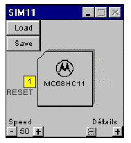
The virtual microcontroller acts
just like a real one.
You have to download a talker into
its memory, before the debugger can communicate with it.
Fortunately the virtual micro is
already delivered with a talker loaded into memory at factory.
You may replace this talker at any
time by another talker using the INITTALKER command of the debugger.
Once the talker is loaded, the debugger
can communicate with the virtual micro by the virtual serial interface
like with any real microcontroller.
The yellow button RESET is the RESET
input of the micro. You may click on it to change its state.
The virtual micro runs all the time
like a real micro does.
The Speed button allows you to select
the relative speed of the microcontroller.
At 50%, the simulator takes the
half of the cpu time of your P.C., leaving the other half to all other
applications running on your P.C.
You can store the state of the virtual
micro into a file using the Save button. The state includes the memory,
the cpu, and the inputs and outputs. Use the Load button to reload a saved
state.
When the simulator is launched,
it looks for a file defaut.sim in the current working directory and in
the BIN directory where the simulator resides. If it finds the file, the
simulator loads the state from this file. The installer places a file default.sim
into the BIN directory, which includes a talker for the virtual microcontroller.
The Details buttons allow you to see more or less details of the microcontroller.
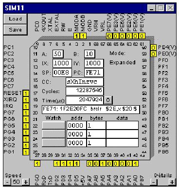
Here you have access to the inputs
and outputs of the chip.
Clicking on a digital input toggles
its state.
You may also change the state of
an analogue input from 0 V to 5 V.
When the program writes to an output,
the state changes in the window.
Ports B, C, and F are not available
in expanded mode.
You may choose the operating mode
by the pins MODA, and MODB and reset the chip using the RESET pin.
The pins IRQ and XIRQ may cause
an interrupt.
The pins PD0 and PD1 are used for
the communication with the debugger. Your application can not use them,
but may send and receive characters by the serial interface (See Debugger,
Interrupts of the talker)
Example
Select the port SIM and a 68HC11F1
in the configuration. Open the file toggled.c.
Compile the file. Use the debugger
to load the file into the virtual chip. Click on GO to start the program.
The program toggles regularly a
LED on output port PG0.
If you set the input PG1 to 0, the
LED toggles faster.
You may also use the Details button,
to open the virtual microcontroller.
If the micro is not in the RESET
state, and the speed is not at 0, you will see that the cpu runs all the
time.
When it does not execute an application
program, it executes the talker, which is waiting for command on the serial
line.
You can the registers of the cpu,
the actual mode, and the machine instruction to be executed next.
You see also the cycles, the cpu
has executed and the elapsed time. You may set these values to zero.
If you select speed 0, you may execute
the program in single step mode.
Do not confuse this single step
mode with the single steps of the debugger. Opening and halting a microcontroller
is only possible with a virtual chip.
The watch lines allow to display
memory and to stop the chip under certain conditions.
Enter the starting address and the
size of a memory region.
Select one of the following modes
with the left button.
Watch
Display memory ( 4 bytes maximum)
Break
Stop the cpu, when the PC enters into the region.
Stop Rd
Stop the cpu, after the cpu has read from this region.
Stop Wr
Stop the cpu, after the cpu has written into this region, or in case of
an input, when it has changed.
Stop RW
StopRd and StopWr.
If you want to use other circuits
around the microcontroller, you must put the chip on a printed circuit
board. The software calls functions from board.dll in the BIN directory.
There are two boards available after
the installation:
board0.dll
68HC11 only
boardcf1.dll
Controlboy F1 including a LCD display and a keyboard (this product is only available directly from Controlord in France)
If you want to change the board, just copy another file to replace board.dll and restart the software.
You may want to write your own board.dll.
Sources of the mentioned boards can be found in the BOARDSRC directory.
You will obviously need a PC tool to create the dll from your source file.
The source file must include the
following functions:
LibMain
Open the DLL
WEP
Close the DLL
BoardOpen()
Open or close the simulator
BoardRead()
Read a byte from the target memory
BoardWrite()
Write a byte to the target memory
Board.dll sends a SIM_PORTCHANGED
message to the simulator when an input changed to update the target memory
and the watch data.
Implementation
Carriers
MC68HC11A0, A1, E0, E1, MC68HC811E2
all PLCC.
MC68HC11F1FN PLCC.
DIP not implemented.
Modes
Boot, single chip, expanded.
Mode Test not implemented.
Registers OPTION, BPROT, HPRIO,
INIT, CONFIG not implemented.
Memory
64k RAM, unprotected in all modes.
The ROM of the 68HC11A8 without
security appears from BF40 to BFFF on mode Boot.
(Motorola M68HC11 Reference Manual
Rev 3, B-2)
Resets and Interrupts
Reset
-external
XIRQ -implemented
IRQ -implemented, low level
Illegal Opcode -implemented
SWI -implemented
SCI -implemented for receive data
Real-time Timer -implemented
others
not implemented
CPU
Registers and instructions implemented
as in Motorola M68HC11 Reference Manual Rev 3, chapters 6 and A.
Parallel Input/ Output
-Implemented for A, B, C, D, E, F, G
with their data direction registers.
-Not implemented: Port B, C handshake,
port G chip selects.
Serial Communications Interface
SCI
-Implemented to communicate with the
debugger.
Analog-to-Digital Converter
-Implemented for the register ADR1 only.
Real Timer
-Implemented.
Serial Peripheral Interface SPI,
Timing System, Pulse Accumulator
-Not implemented.